17 September 2011

Project "Emerson/Baird Wondergram"


i bought this thing online and waited a long time for it to ship from halfway around the world. it was a gamble because i know from the seller that the motor on the player spins but the sound doesn't work at all and it would be worthless as a record player if it didn't make any noise whatsoever!


so anyway, this is an Emerson Wondergram made in the 1960's. as you can see it is a battery powered portable record player that plays both 33rpm and 45rpm discs...a 'Wonder' for its time and weighs a 'gram' (ok not really, but see what i did there? hurhurhurhur) it comes with a holder on the top cover for a 45rpm adapter too which is pretty neat.

*EDIT* i totally forgot to mention that this player originates from the UK made by a company called Baird, but sold in the USA under the Emerson brand. the player has the Baird brand on the bottom plate that say "Baird, Made in England, A Camp Bird Product" (what is Camp Bird anyway?)

*EDIT* in case you're wondering the size of this, here's a tissue box for comparison:


when it first arrived, the motor spins but sounded like a jackhammer. when i tried to put the needle on a record, the entire player just ground to a halt. obviously the motor just didn't have the juice and was in need of some restoring.


opening it up isn't hard, just remove all the screws you see on the outer shell and you can lift the innards all out. as you can see from the pictures above, this thing was hideously dirty and dusty inside. the dampening sponges under the speaker and the motor were hardened and flaking debris each time i moved it, in short it was a real mess.


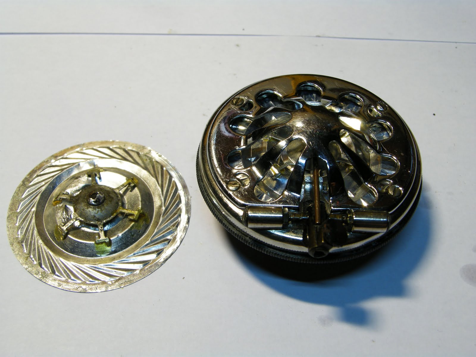
the way the motor runs the records at 33 and 45rpm is a real curious thing as it doesn't 'directly' spin the record like in a normal player. you can see the motor in the picture above and the shaft is touching one of the two rubber wheels. when the motor spins, it turns both wheels as well. the clever bit is that both wheels are set at different distances and this enables it to play records at either 33 or 45rpm.

when you put a 45rpm record that has a smaller diameter than a 33rpm, it would only touch the inner wheel that spins the record faster since the wheel is nearer the center of the record. when you put a 33rpm disc it will touch the outer wheel. since the 33rpm wheel is further from the center of the record, a 33rpm record would not touch the 45rpm wheel at all because that wheel is smaller...ingenious!

after inspecting the circuit, checking for continuity, dry solders, cracked solders, broken wires, etc etc...i spotted this in the picture below:


well there's your problem! the capacitor across the speaker is obviously blown and its guts have leaked out. it needs to be replaced.


as you can see, i have a big thumb. and also this capacitor is 100 micro farads and rated for 6 volts. my brother was kind enough to explain to me what this capacitor is for (to convert a DC signal into an AC one so that the speaker would work) and even drew a diagram out.


the entire circuit in the player only has 3 capacitors. one going to the speaker (100ufF, one on the motor (100uF) and one on the main circuit board (10uF). i decided to change all 3 to modern day equivalents and although that's not the purist way to restore antiques, it is hard to trust 40 year old electronic components to last very long nowadays (if you can find them!).

the picture below shows the difference in size of the original capacitor and its modern day equivalent. i couldn't get my hands on a 6V rated one and got a 16V one (it doesn't matter).


while i was changing the capacitors, i managed to break some wires just by moving the player around my desk. the wires were all corroded and i replaced all the wires (not a lot, about 7 all in all) with new ones.

so its out with the old and in with the new!


the solders in the picture above shows that this machine was obviously assembled by hand. i used new solder for the new wires, and resoldered all the old solders as well just in case there were dry...i figured this would ensure there were no breaks in the circuit and give the player another few decades of life.


the single speaker has the brand 'ELAC', i googled the brand and apparently it's still around today...they must have partnered with Emerson back in the day when this player was produced.

on the left side in the picture above you can see the auto stop mechanism. when the arm reaches the end of the record the mechanism will push away a metal contact, opening the circuit and stopping the player completely.

after resoldering, rewiring and replacing the capacitors, i worked on the cosmetics of the player because it was heinously dirty! a quick polish with the novus plastic polisher (previously used on the westclox alarm clock) and it gave the shell a nice sheen to it. (before and after on the left and right respectively)


ok...granted it's not much of a difference but it'll take ages to buff the scratches away, i'll leave them there for the 'rugged' look.

*EDIT* you can see the Baird brand between the two upper legs in the picture above

i managed to order a new needle online to replace the worn out one that came with the player, no prizes for guessing which is the new and old needle.


in case you're looking for the needle for this machine, it is an electro-voice 51 (ev51). it is a ceramic cartridge and has 2 sapphire tipped LP points (so more bang for your buck because its two needles in one!).


so anyway all that was left was to slap in new fresh batteries (4 x C-sized, in case you're wondering) and test it out...and it works!


18 August 2011

Project "His Master's Voice Soundbox No.5B"


the current soundbox/reproducer i have on my gramophone was bought on ebay from india and it arrived in pretty bad shape. for starters, the diaphragm had a hole in it and the rubber connector crumbled into dust when i fitted it on to the tonearm.

i scrounged the world (online) for spare parts and managed to get a new rubber connector a few months ago but i had no luck with finding a replacement diaphragm...UNTIL LAST WEEK!!

i would like to say a big thank you to Mr. Ken Priestley of the U.K for his expertise. i managed to find a new diaphragm from him and those of you looking for spare parts for your gramophone can look for him at his website: http://www.fonograf.talktalk.net/

anyway i ordered a new diaphragm from him last week and it arrived here in singapore within 8 days (as fast as international mail gets around these parts).


he packed it really nicely with cardboard spacer preventing the diaphragm from warping/tearing.

anyway...if you are interested to do a diaphragm replacement on a HMV 5b soundbox, this is how i did it:


unscrew all four screws on the back of the soundbox and the rear (black) plate comes right off. in the picture above, you can see the felt gasket that is fitted around the edges of the diaphragm to make it more airtight. you can see the lousy repair job i did on my old diaphragm...i basically glued aluminum foil around the hole to patch it up!


remove the four screws on the front plate of the soundbox. use a pair of pliers to hold the nut on the needle bar and gently unscrew the pivot screw (both of them). at this point the diaphragm and the needle bar can be gingerly removed from what's left of the soundbox.


you should then be left with just the diaphragm and needle bar as shown in the picture above. the needle bar on mine was soldered on to the spider. you will obviously need a soldering iron to melt the solder, so be extra careful during this step! i put a small precision screwdriver to hold the diaphragm in place as i desoldered the needle bar from the spider like so:


look at the difference in condition between my old tattered diaphragm as compared to the new one, no prizes for guessing which is which!


i soldered the needle bar on to the new diaphragm, making sure to position it in the center of the spider. the soundbox can now be reassembled by working backwards from the steps shown above. if you find the needle bar is out of position after fitting the diaphragm into the soundbox, it can be repositioned by simply touching the soldering iron to the solder and small adjustments can then be made.


i fitted the soundbox back on to the gramophone and played a few records. one of the obvious improvements i noticed straightaway was the increase in volume and overall fullness of the music, no more wasted energy due to air leaks! voices were clearer, strings were cleaner...its a pity i couldn't have gotten a perfect diaphragm sooner, but i'm very happy that i finally do!


11 August 2011

Project "Wehrle Polo Alarm Clock"


i saw this alarm clock at a flea market and noticed it had a second hand on the bottom. i'm not an expert in any way with clocks/watches but it seemed like a nice thing to have on an antique mechanical alarm clock so i bought it. it also has the words "made in germany" at the bottom so it should be of some value. (right? german efficiency and all that?)


it kept stopping on its own after every five minutes, so it was in need of a cleaning and tuning.

the problem with this clock is that unlike other 'normal' alarm clocks, this one had its back crimped on to the body. that makes it a few hundredfold harder to open. i applied some oil around the edges and slowly eased the back plate off the body with a small screwdriver.

another problem was that the knobs at the back could all be unscrewed except for one: the time adjustment knob which is in the center. it obviously couldn't be unscrewed because you can turn the knob both clockwise and anticlockwise to adjust the time.

to remove the knob you will have to pry open the back plate (like in the picture below) and use one pair of pliers to hold the shaft that it is attached to on the inside and another pair of pliers to slowly pull the knob out. (dabbing some oil would be good, the shaft in my clock had some rust on it and was nearly fused to the knob)


remove the two metal feet from the bottom by simply unscrewing them from the body, once that is done the whole back plate can be removed.


the only thing holding the clockwork to the body now is the snooze button up on top. the button is held in place by a circlip shown in the picture below, pull the clip out (gently) with a small pair of pliers and the button can be removed.


once the snooze button is removed, the snooze button holder can also be removed and the clockwork comes right off the body. the snooze button assembly is really small and easy to lose so make sure you put it somewhere safe!


i can't really explain much about the gears, all i can say after looking closely at the mechanism i managed to identify the gears that were affecting the system and a few dabs of light machine oil here and there made the clock run smoothly without stopping (overnight) so it was better than when i first got it.

this video shows how the snooze button works:


the top knob sets the time the alarm will ring. when it does ring and you press the snooze button, the ringing will stop and the button stays down. it will pop back up only if the alarm spring is rewound (which is what people will usually do before they go to bed). it doesn't sound like it's ringing because the back plate has to be on...it is definitely loud enough to wake someone up unless they're in a coma.


the glass (not plastic) lens simply needed a good cleaning with liquid glass cleaner.


before:


after:


so now it was ready to be put back together!


on a side note: the back plate kind of looks like a sad, four-eyed alien, don't it?


i think it looks slightly more brand new now...but the body gives it away. still...it's a nice clock to add to my collection of old stuff!


17 May 2011

Project "His Master's Voice Gramophone Model 102 Disassembly"

i have been noticing that most of the people stumbling upon this blog are actually looking for information about the HMV 102 gramophone i did up a few months ago...today i decided to do a short instructional on how to strip the entire thing down. (please click on the pictures to get a much bigger image!)

you will obviously need a flat head screwdriver, remove all the screws at the side and the two on the tonearm clip. remove the three screws on the tonearm base as well as having the tonearm out of the way would ensure you don't accidentally wreck it while moving the thing around. remove the circlip on the turntable and lift the whole thing off the gramophone.


while doing all this, make sure you put all the screws and loose bits into a container of some sort as 50 year old screws are somewhat quite hard to find nowadays in the event one of them drops somewhere and disappear forever.


once all the screws are..er..unscrewed, remove the whole bottom portion (i call this the motorboard) out of the 'briefcase' portion and put the 'briefcase' somewhere safe (put a cloth below as it might be pretty dirty and oily). the next step is to unscrew the four biggest screws left on the motorboard (the ones with the washers on them) and now the motor will fall (gently) out of the motorboard.


turn the motor upside down and you'll see three nuts that need to be removed. use either a small spanner or a pair of pliers and keep these in your safe place.


the bottom plate of the motor comes right off, but be careful at this point as the spring might/should have some power left uncoiled and might jump slightly if you're not careful (fingers beware).  the spring is kept inside the round container you see in the picture below, you would notice that my spring container has white tape all over it, and i'll explain why later.


the spring container can be removed by simply pulling it upwards off the center shaft. the container is kept shut by a retaining wire that is hard as hell to remove, and once removed, hard as hell to put back without accidentally ruining it (which is what i did). the last time i opened this was to install a new spring, and it looks okay so i won't be showing how to remove it in this blog post (it's a b*tch, but it can be done with lots of patience and/or cussing).


this part of the motor shown in the picture below is the governor and this is what ensures the spring doesn't uncoil all at once with a bang. how it works is that as the spring unwinds, the governor spins and the three metal weights you see would move outwards due to centrifugal force. as they move outwards, they move the disc towards the stopper (the black piece resting on the disc in the picture). the stopper restricts the distance the disc can move and the governor weights can't move any further and can't spin any faster either, thus giving you the desired speed. i realize i can't put it nicely in words so i provided a video for your better understanding.


so, now to put back everything together! starting with the spring container, if and when you manage to get the retaining wire back into the little groove that originally held it in place, it will probably be out of shape and spring out of position the moment you let go and that's where the tape comes in!


put the spring back onto its shaft. put the baseplate back on the motor. screw the nuts back onto the baseplate. put the motor back into the motorboard, and you will get to the picture below (whew!). now, to calibrate the speed of the motor so that it spins at 78rpm when the speed selector is set at..well..78rpm, you'll have to physically move the speed selector by hand as shown below. moving the speed selector to your right would make your speed selection faster, and moving it to the left would make everything slower...you'll have to do it for yourself to know what i mean.


you can check your speed by using a strobe disc with the same hertz as your power mains. as i am in singapore, this would be 60hz. turn on some lights and shine them on the disc while the turntable is spinning. if the lines at the 78rpm mark are stationary then you know you're at 78rpm! takes some trial and error but you'll eventually get there!


that's about it, i tip my hat (if i had one) to the engineers at HMV who designed this simple yet complex machine!

here's 'diamonds are a girl's best friend' by jo stafford:


(link to page 1/3 of HMV restoration)