i have been spending the past few weeks integrating and programming the SolderTime2 to work with a BMP085 barometric pressure and temperature sensor and it finally works the way i want it to. it now functions like a (very) poor man's Tissot T-Touch (okay..just the barometric functions and not the touch functions).
the I2C port on the SolderTime2 makes it possible to add a whole lot of other I2C sensors (gyroscope, compass, humidity) to the watch as long as the additional modifications to the program does not bust the total amount of memory available on the watch which is 32kbytes.
i removed the worm animation mode as well as the scrolling text mode on the watch to free up some space in the flash and i have already used up about 26kbytes but i think it is largely due to my inefficient code! (still a work in progress)
amazingly i also found that a tin of Milton Pastilles Candy (commonly sold in Singapore) has the exact diameter of the watch's front cover, give or take a millimeter or two, and can be modified to fit the watch with the additional sensor. i haven't worked on the tin yet but that will come later on when i have the time to get around to do it.
the positive end of the battery goes to Vin and the negative goes to ground. after some simple circuit tracing, i found that the SCA and SCL ports can be wired to from the two resistors on the top left of the watch. the left resistor being SCL and the right resistor being SCA.
the ground of both batteries have to be connected together for the sensor to be able to recognize the data coming from the watch. i did not know this and spent a long time troubleshooting before my brother explained to me that it is required otherwise the sensor has no common reference to zero and any signal i send over is unrecognized. (wasted good portion of my life finding that out)
*EDIT* i forgot to mention that the BMP085 sensor board from adafruit includes 10k pullup resistors for the I2C ports and they need to be removed by simply touching a solder to the resistor and taking them off. 10k pullup resistors are already provided on the watch, in fact the modification wires are soldered to the resistors themselves.
i have programmed the watch with an additional mode "ALT" to display the altitude above sea level in meters and also to be able to set the localized sea level pressure (obtained from any local country's weather website, also known as QNH). in this case, the pressure in singapore at the time of making the video posted at the beginning of this blog post was 1,008.14mb and when i set it to that pressure it displays 48.5 meters above sea level which should be correct as my location was situated on top of a hill.
it also has a mode "TEMP" displays the current temperature of the sensor, and the temperature goes up when i put my finger on the back of the sensor's PCB.
i will be happy to share the codes with anyone interested to make this modification to their SolderTime2, just drop me an email and i will send them over!
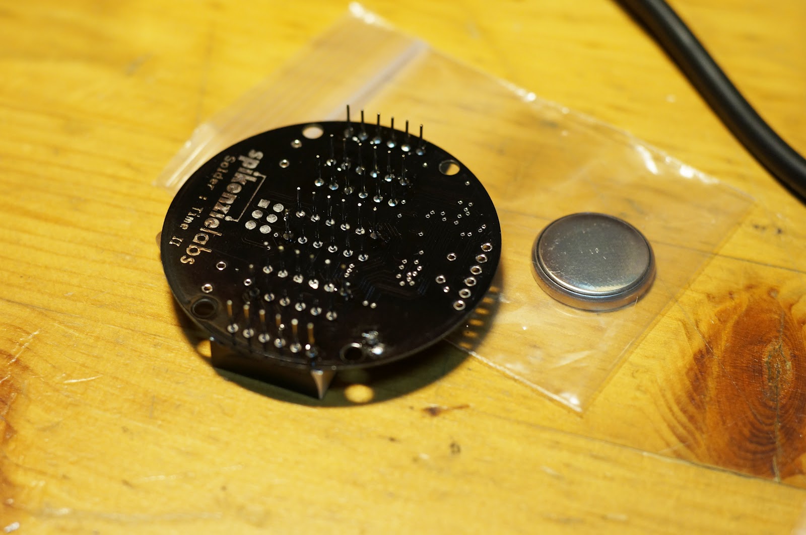
this was a DIY watch kit i bought a few weeks ago that finally arrived here yesterday. it is basically a microprocessor programmed and designed to function as a watch. it is completely 'hackable' which means that you can create and flash your own programs to the microprocessor and make it do whatever your creativity allows you to do.
its very easy to assemble and all i needed was a soldering iron, solder, and a pair of wire cutters. SpikenzieLabs have very clear and easy to understand instructions on their website here:
it cost $59.95 USD for the kit, and if you want to upload your own sketches to the microprocessor you will need an FTDI cable. since i didn't have one around i bought one from adafruit as well here:
it's no rolex obviously...but it is a great introduction to C++ microprocessor programming!
you only need to install the battery holder, buzzer, two push buttons and four LED arrays and you're ready to go.
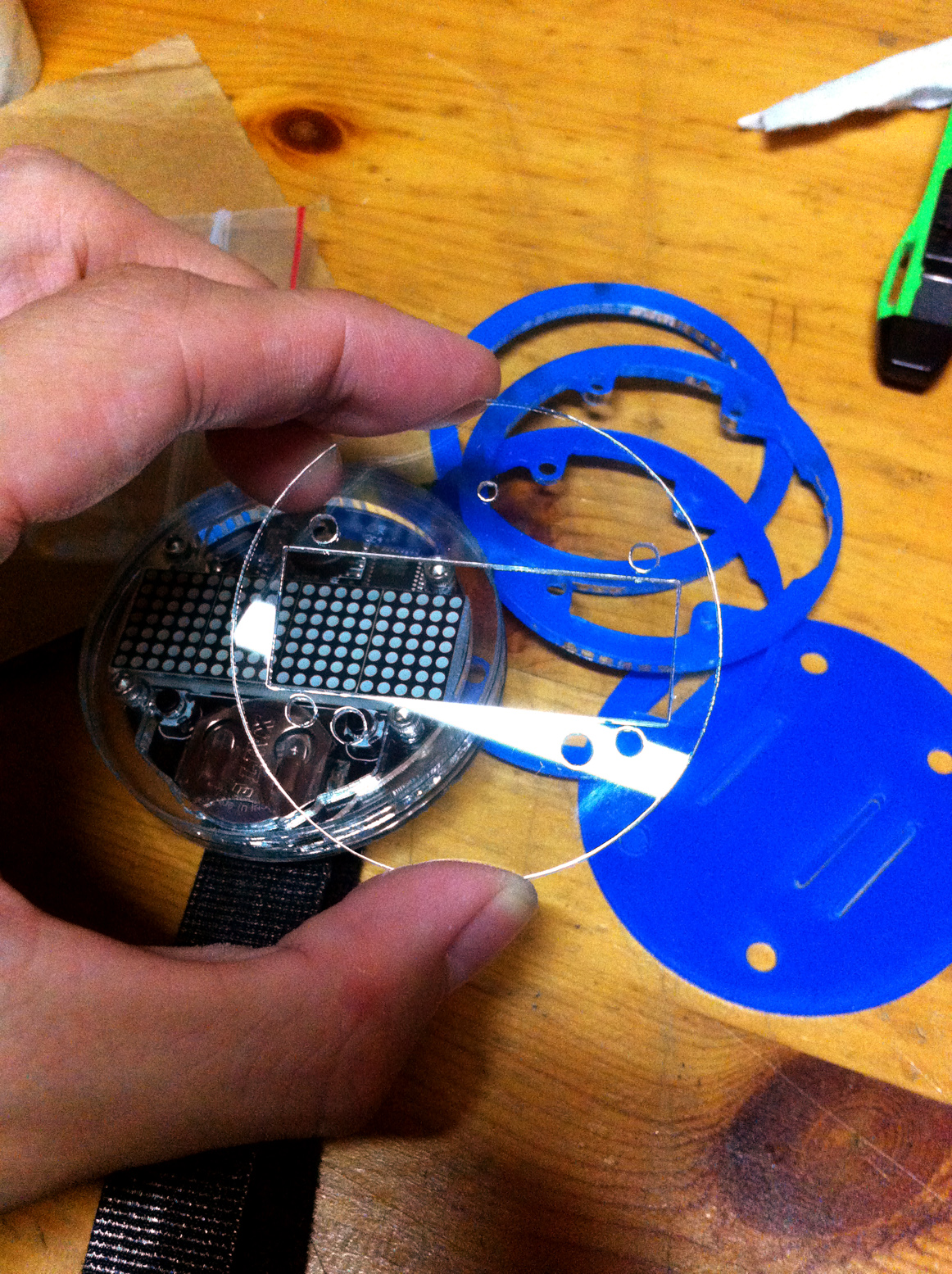
UNFORTUNATELY for me, the acrylic top plate of my watch was cracked on two of the four supports holding the plate together. the plate is still held together but i'm afraid any sort of pressure would snap it easily. i sent out an email to adafruit in hopes that they will send me a replacement or something but i don't know what is their policy on this. the other pieces of acrylic are fine but the top piece is the thinnest and might have cracked during packaging or in transit. i will update this post accordingly if they get back to me with a replacement.
*UPDATE* they got back to me really quick! and they've agreed to send me a new replacement plastics kit! *UPDATE 2* i have received the replacement kit today! 10 days after they said they'd ship another to me. i won't be removing the issue about the cracked acrylic because i want everyone to know what great customer support Spikenzielabs have given me! I have plans to add an additional I2C device to the watch in the coming weeks and would probably make my own casing for the watch but I will definitely be reusing the front plate for my next project.
that aside, the watch worked fine when i put the battery in. the latest sketch was already pre-installed into the watch. i followed the instructions on SpikenzieLab's website and got the Arduino IDE on my laptop and spent some time reading and understanding the codes. if you have done any sort of microcontroller programming before it should be easy for you to understand how the program works. i have never touched any sort of Arduino before but it is all pretty straightforwards.
the programming (FTDI) port is located on the back of the watch and to upload your own sketch you just need to stick the pins of the FTDI Friend (for my case) into the port. make sure the correct pins go into the correct ports! the FTDI Friend needs some basic setting up on your computer as well but again, the instructions can be found online and is easy to follow:
the LEDs on the FTDI Friend will blink if the sketch is being uploaded. the pins do not click snugly into the programming port and the website suggests using a light diagonal force to ensure they make contact with the connectors and this is what i did in the picture above.
for a quick demonstration i just changed the scrolling text message to "Hello World" and set a slower scroll speed than the default one. i uploaded the sketch and sure enough the scrolling text showed the change:
this watch is HUGE and honestly hard to match with any outfit unless you're going to an electronics themed club or party. but as i mentioned before it is a very interesting way to dabble with simple programming and you get a cool watch out of it all!
i've always had a problem with dirty vinyl records and I know that playing records with all the muck in the grooves will eventually ruin both the record and the stylus of the player.
there are actually specialized vinyl record cleaners available commercially but they range from the simple Spin Clean machine that costs $200SGD (http://www.spincleanrecordwasher.com/) to the extravagant Nitty Gritty that costs anywhere from $600SGD to $1700SGD (http://www.nittygrittyinc.com/).
i don't have enough dough to spare for either and thus i decided to see if i could make my own machine and went down to the nearby Salvation Army thrift store and got a used vacuum cleaner to salvage the vacuum motor.
the machine case is made of 12mm Perspex which is slightly overqualified for this project (i would've used wood) but that was all that was available to work at that moment because there was some lying around. it adds the 'cool factor' of being able to see everything in operation when the motor is turned on though!
my father very kindly took my very crude and simple design and upgraded it. he drew the design up in AUTOCAD and used a CNC router to precision cut the case of the machine and i had the simple job of putting it all together with screws.
the platter and clamp is also made out of the same perspex. the spindle was machined using a lathe and attached to a simple ball bearing. the clamp works well to turn the record but unfortunately it is too light to do its job during the vacuuming phase and i have to turn the record manually by hand at the edges while vacuuming. i glued on hardened felt to the platter as well as clamp to give it some grip on the record when turning it.
the vacuum motor is fixed in the middle of the case and made to be as airtight as possible for the best possible vacuum efficiency. the exhaust side of the case has grilles cut into the perspex for the air to exit. the motor speed was found to be too powerful for this application and a motor speed control card was added to limit the power of the motor in operation.
a glass jar is placed at the intake with two holes cut on the top and some water is added to the jar so that any dirt and dust will settle in the water without going into the vacuum motor. there was no need for an exhaust pipe that extends to the mouth of the vacuum motor as the motor is strong enough to suck in air just by placing the jar in the compartment in front of the motor.
the side of the record cleaning machine is held by two clips and lined with rubber gaskets. this is so that it will be easy to remove the jar for cleaning without having a need to unscrew the supports.
the side of the machine also features an adjustable bleed air port. this was put in in anticipation of the motor being too strong and this sliding port would allow me to adjust the power of the motor. but with the addition of the motor control card this port is actually quite redundant now.
the vacuum nozzle is made using simple PVC pipes. a 3mm slot was cut into the pipe and lined with high quality velvet.
the record cleaning fluid is also DIY, made with 3 parts deionised water, 1 part isopropyl alcohol and 1 drop of dishwashing fluid. the brush is a good quality wet cleaning brush with sturdy nylon bristles to get the grit and muck out of the grooves and the vacuum will suck that all away.
if you ever intend to make one of these, it will be best if you get a smaller motor or one that has a controllable speed. the motor speed control card was only added after the initial design and if i knew it was going to be included i would have made the box a lot smaller than it is now (40cm x 25cm x 25cm).
i actually bought this player sometime last year from a seller on ebay without having any prior knowledge on both the brand (Mitchell) and the player. it wasn't in working condition and he was selling it at quite a cheap price (all in all plus shipping about $60 SGD). it could play 33, 45 and 78rpm records and it was electric so i decided to get it mainly to play 78's because although the gramophone i have could play 78's, its heavy tonearm would eventually ruin the records after many plays. this player had an inbuilt loudspeaker and would be ideal for listening to 78's (especially the more modern non-acoustically recorded ones).
i tried for many days to search online for this brand of player as well as the specific model, Mitchell Model 1265, but to no avail. there were no examples of it anywhere and those that i emailed had never heard of this model before. it comes in a plain suitcase form as shown below:
when it arrived, i realized that i had made quite a big mistake. the player was made to be played in the USA and accepted only 120V mains supply at 60Hz whereas where i am (Singapore), it is 240V at 50Hz. while i could easily get a transformer to convert 240V to 120V, the difference in mains frequency meant that the motor of the player would not spin at the correct speed. the player also emitted a loud hum when i turned it on, and when i attempted to touch the tonearm i got a good shock from it.
i put the player into the corner of my room and never touched it for a few months while i occasionally went online to search for any other examples of the player and the brand (none at all, if you were wondering).
a few months ago i did take the player apart and took a good look at its innards...and it was a mess...and unfortunately at that time my compact camera that i had always used to take the pictures used in this blog decided to give up the ghost and i was left with just my phone's camera to take pictures and i didn't do a good job documenting it.
it wasn't pretty...
to summarize quickly, i had to clean out the decades worth of dust and mold inside the suitcase and then replace the parts that were the most likely to have failed over the years. After taking a good look around, it was clear that the only components were the capacitors and the vacuum tube. in the picture above, i already replaced the biggest capacitor in the amplifier (the silver cylinder thing). it is actually 3 capacitors in one big cylinder with a common ground.
on the cylinder it is written:
GUDEMAN (the brand)
MEL - 42110 (the part number i guess?)
RED 40MFD 150VDC
RED 40MFD 150VDC
BLU 20MFD 25VDC
BLACK COM - NEG
so this means that the respective wire colors are connected to capacitors of that value and voltage rating inside the cylinder. i bought two 47uF capacitors rated for 160VDC and one 22uF capacitor rated at 50VDC as replacements and soldered the connections together. you can see the difference in sizes a few decades of technology has given us:
there was another capacitor in the amplifier and it was a paper-oil capacitor with a wax coating. after researching online, it was clear that this capacitor definitely had to be replaced because paper capacitors are well known to fail from old age.
i bought a modern aluminium capacitor with the same ratings, .1MFD (100uF) and rated for 200VDC and soldered it into place.
the amplifier has one 25L6GT vacuum tube and it glows orange when the player is powered up. i know next to nothing about vacuum tubes and i didn't fiddle with it. i know enough to identify that if the tube is glowing in colors other than red-orange then it should be discarded, and also that if the top has turned a milky white instead of transparent then it should also be replaced. this one had none of the above and so i kept it in place.
the loudspeaker on the player had a small tear on the cloth (more like paper) diaphragm and i did a quick fix by sticking a small piece of paper with some light glue over the hole. i've done this before and it works well...it's enough to stop air from leaking out and the sound will still be as good as a normal diaphragm.
the main problem after all this was that the motor still doesn't spin at the correct speeds. a record player is worthless if the songs it plays are all in slo-mo, unless you intend to use it in a horror house or something...
there is a knob on the side of the turntable to select the speed of the player. when it is in the off position, the motor still runs.
as you move the knob from one setting to the other, it adjusts the position of the grey wheel shown in the picture above. the wheel touches the shaft of the motor which has three different thicknesses. this enables the speed of the grey wheel to change while the speed of the motor stays constant. (think of it as a gearing system). to make the wheel turn at a faster speed, i put different thicknesses of heat shrink tubing over the shaft to make it thicker and allow the grey wheel to turn faster.
after a few hours of trial and error, i found one type of heat shrink tubing that added enough thickness to the shaft to make it spin at 78rpm when the knob is at 78. unfortunately, i could not get the correct shaft thickness for the 33 and 45rpm speeds but 78 is good enough for me!
again, if you're wondering how to verify your record player's rpm, just use a strobe disc that can be found on the internet and print it out. i've been using the same disc to calibrate my gramophone and it has been accurate enough so far.
as my country's mains supply is 50hz, any light will flicker at that frequency and when the bars of the 50hz strobe disc at the rpm you are calibrating for seem to be stationary, then you know that you have the correct rpm.
the last thing that needed to be replaced was the cartridge. the original one that came with the player was an Astatic cartridge that had the numbers "16L3" on it.
again, there wasn't much information available about this cartridge online. i sent out emails to a few different turntable needle stores and only one had the exact same cartridge available but was selling it at $100++SGD which was insane.
i finally stumbled upon this site: http://www.needles4turntables.com/ceramic.htm and sent an email asking if it will work with my player. he replied and recommended that i get the Pfanstiehl P-51 cartridge with the 3mil needle that will work well with 78rpm records.
he shipped it out the day i made the order and it arrived in 7 days (USA to Singapore) and i proceeded to connect it to the tonearm.
the reason for the shoddy wiring you see in the picture above was because the new cartridge is a lot smaller than the old one, thus the wires could not reach the connections. i extended the wiring by splicing new wires to the old one but i didn't have wires of the same thickness, thus resulting in the frankenstein-ish work...
i turned the player on and used a toothpick to lightly brush the needle on the cartridge and there was sound coming out of the player's speaker!
i put the player back together and put on a 78 record and it came aliveeeeeeeeeeeeeeeeeeeeeeeeeeeeeeee!